Simulation-driven design.
Graded lattices: more material where the part needs it
A uniform lattice treats every point of the part the same. A graded lattice changes its wall thickness, or its cell size, across the part, following a field you choose.
Open IMPLICIT Free, in the browser. No installation, no account to start.
Fields that can drive the lattice
Fields can be combined, inverted and shaped with a mapping curve, and zones can be painted with their own thickness.
- Geometry: a linear gradient along an axis, the distance to the surface, and attractors (points that add material around them).
- Simulation: von Mises stress from FEA, or temperature from a steady-state thermal analysis.
- External data: a greyscale or colour-mapped image (PNG or JPG), or a numeric CSV such as a pressure map, projected onto the part.
- The result of an optimisation for a target mass.
Thickness, cell size or lattice type
The field usually sets the wall thickness, or the beam diameter, between a minimum and a maximum. It can also grade the cell size, or blend smoothly from one TPMS to another, for example from gyroid to Schwarz P, along an axis, around a point or following the field.
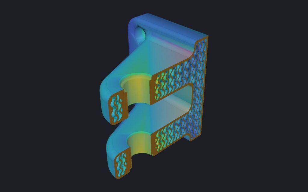
In the example hinge bracket, the stress grades an 8 mm gyroid between 0.75 and 2 mm. Verify then repeated the load case on the lattice: a safety factor of 3.85, against 4.24 for the solid part (1 mm voxel, indicative).
Images and pressure maps
An image or a CSV matrix is reduced to at most 256 × 256 values, smoothed, and projected along X, Y or Z, fitted to the part or at a scale you set. The data travels inside the project and is never uploaded. It is how the custom insole template uses pressure maps.
A simple gradient, the distance to the surface and attractors export on the Free plan. Grading by a simulation, an image or a pressure map, the mapping curve, zones and graded cell size are Pro tools: you can design them on any plan, and exporting them is Pro.
Frequently asked questions
Does grading by stress make the part stronger?
It moves material towards the areas with more stress, which usually helps. Whether the part is strong enough is a separate check: run Verify (Pro) on the lattice, and test critical parts.
Will the transition show steps?
Gradients, attractors, the distance to the surface on simple shapes, and images change the wall continuously. On TPMS lattices, a stress, temperature or optimisation result is applied in up to 8 bands, so the wall changes in small steps; on beam lattices it is read at every node.
Can I use a temperature result?
Yes. A steady-state thermal analysis (Pro) gives a temperature field that can drive the wall like the stress does.
Which images work best?
Greyscale PNG or JPG, or a colour map with a Jet, Viridis or Turbo legend. Range, gamma, inversion and smoothing are adjustable.
Open IMPLICIT Free, in the browser. No installation, no account to start.
What you can do with IMPLICIT
- Lattice generatorGyroid and other TPMS, beam cells, Voronoi and spinodal.
- Topology optimisationThe stiffest layout for the material you allow.
- FEA for 3D printingStress, displacement and safety factor in the browser.
- Custom insolesFrom foot size, pressure map or scan to a lattice insole.
- Embossing and texturesText, logos and patterns, raised or engraved.
- EducationEvery Pro feature, free, for learning and research.